
 |
|||||

| Back to Aerocon |
Examples of Test Stands
This is an old heritage website. Please follow the link below to our If you'd like to contribute your test stand please drop me an email, any and all are welcome. |
Aerocon Systems |
|

|
Shown left is the Aerocon Systems 20, 50, 100 KG-F vertical test stand using a heavy duty base, a single point (cantilever) load cell, and some plumbing parts. More info on our new site |
| |
|
 |
This is the easiest and simplest test stand that we at Aerocon offer for larger motors. Relatively light weight but robust, this stand is portable and repairable due to its modular construction. Generally used for motors from 1" to 4" in diameter up to approximately 1,500 pounds thrust. More info on our new site |
Ultra Simple Bucket Stand By clicking the image on the left you'll see a simple test stand using a 5 gallon bucket, a chunk of aluminum I-beam, some concrete, and a single point cantilever cell. This unit is designed to handle motors up to 45 pounds thrust and the Aerocon 20kG load cell. You can easily make this at home with parts you have hanging around. Feel free to print out this file and make one of your own. |
|


Courtesy of AeroRocket
http://www.aerorocket.com/rmts.html
RMTS DEVELOPMENT
The development of the Rocket Motor Test Stand (RMTS) was undertaken to
better define the thrust-time characteristics of rocket motors for improved
flight performance analysis. An AeroTech RMS-38/360 rocket motor using
an I161-6w reload kit was hot fire tested using the RMTS on March 28,
1998. This system is capable of recording the thrust-time characteristics
of rocket motors generating up to 331 pounds of maximum thrust. Overall
test-bed dimensions for the RMTS are 19 5/8" long x 12" wide x 16 1/2"
high.

The RMTS is fabricated from 6061-T6 aluminum using 3/4" thick plate for the rocket motor mounting components of the main chassis. The rocket motor translation plate is supported by two pairs of linear bushings which slide on two precision steel shafts. Shaft alignment is maintained by two 2" square shaft support members bolted to a 1/4" thick x 19 5/8" long x 12" wide plate. The 1/4" plate is bolted to two 3 1/2" x 3 1/2" x 25 1/2" wood beams mounted on two concrete blocks. Rocket motor thrust is measured by a Celtron single-point load cell with a rated safe overload of 331 pounds. A 12 volt, 4 AH lead-acid battery is used to excite the strain gage circuitry in the load cell. The Celtron load cell has a full scale output of 2.0 mV/V. Finally, a DATAQ Instruments data acqusition module is used to record the thrust-time waveform to a laptop computer located 100 feet from the RMTS. The DATAQ data acqusition module is a 12 bit, 2 channel A/D converter and was selected because it was inexpensive ($99.00) and could easily connect to the RS-232 serial port on a standard laptop computer. In addition, if required this 2 channel device can be used to measure any two combinations of thrust, temperature and pressure.

aRocket New Mexico Test Facility
Ray Calkins
http://www.arocket.org/projects/hybrid/

click to enlarge image
http://www.arocket.org/testand
http://www.arocket.org/testand/latest.htm

click to enlarge image
Apogee Motors
View a static test firing of an Apogee Micro Motor.

http://www.apogeerockets.com/micro_motor_burn_movie.asp
American Space and Propulsion - SORAC -
This is the very first test stand in 1999. It has since been rebuilt.
click to enlarge image
In this shot you can see the load cell mounted to the steel C channel.
The steel run Tee which feeds the head end of the motor and is connected
to the nitrous run bottle.
The stand was made from unistrut and sunk into the ground.

click to enlarge image
Here you can see the nitrous run bottle which is a CO2 bottle with a
1" nipple welded
to the bottom and fed from the block house via the white plastic tube.
To the left of the
bottom nipple is a pneumatically operated ball valve.
Motor was intended to produce approximately 1500 lbf for 3 seconds.
AspireSpace
http://www.aspirespace.org.uk
Rick Newlands, Chairman
The Aspire hybrid test stand is designed to comfortably handle our H20 Lox/plastic hybrid's 2000 Newtons (450 lbf) thrust, and our larger proposed H120.
The rocket is mounted in a tie-restrained cradle that translated on
rollers against a loadcell.
It may look crude, but it dampens the structural vibration from the
cradle.
The rails under the rollers are bolted directly into the concrete.
The rig currently has three pressure sensors, a few thermocouples, and
the loadcell.
All the valves are remotely electrically actuated from the bunker.

Charles Barnett

http://www.texnet.net/ccent/rockets/TestStand/TestStand.htm
I was aware of how hydraulic pressure is used to measure force and weight.
I
subsequently saw the hydraulic cylinder test stand on Richard
Nakka's site
and wanted to see just how inexpensively something similar could be
built in
PVC.
The accuracy of the PVC stand is very good but it takes time to reduce
the
data frame by frame from a video recorder and then type it into a
spreadsheet. Once calibrated, and kept clean, a hydraulic stand
is always as
correct as the pressure gauge. The first time we compared a test
curve from
the test stand to one produced with a load cell, we found that the
shape was
identical. Scaling, you could lay one on top of the other.
However, the
electronic load cell was not calibrated properly and showed only about
half
of the real thrust. Calibration fixed the problem with the electronic
load
cell. So, I've learned to trust the hydraulic version more
than the
electronic ones. However, considering time, ease of use
and discrimination
below 1/30 sec, the electronic load cells are vastly superior.
Marlin
Philyaw's hydraulic test stand
Tom Binford


Here's what I use. The small motor holder generated the above
thrust curve. The image below is a larger version of the same
holder.
In both cases the motor presses directly against the load cell. In the
big motor
holder, the vertical wood piece extends about 24" into the ground.
The
output from the load cell is amplified to 0-5V, run through 1000 feet
of
shielded cable to an A/D card in a laptop. With drivers from the A/D
card vendor, I wrote the acquisition software in Visual Basic. All
analog signals are fully differential.

Blue Sky
http://www.novalab.org/rockets/stand1.htm

The Static Test Stand (STS) was designed to aid in propellant development, as well as for static motor testing. It has proven to be very flexible and with addition of appropriate accessories, it was utilized for a wide variety of applications ranging from ignition research to thrust vector control experiments.
Alex Bruccoleri
Alexander.R.Bruccoleri "at" Dartmouth.EDU
This test stand was built as a First-Year summer research project at Dartmouth College. The budget was a $1,000 and the stand is built for rocket motors up to 1,000 lbs. The majority of the stand was built from 1010 8020 Aluminum extrusion and 1/4" and 3/8" Aluminum plates. I did one test with the stand (Aerotech I284) at a Tripoli launch in Cobleskill NY. I have recently been given permission near Dartmouth to build a foundation to mount the stand. At the the time of the initial test the the stand was just buried with "feet" mounted on it which was sufficient for small motors. (The diagonal struts will be mounted to the foundation when a permanent base is in the ground.) In the coming months the stand will hopefully be used to test new Hybrid motors and possibly solids and liquids. Alex
 |
 |
Click to Enlarge Images |
Bruccoleri Graph I284 Motor |


Russ Bruner
Hybrid test stand


Danish Space Challenge
http://www.mainstage.dk/spacechallenge/ |
 |
 |
 |
|
|
|
At the moment the DSC stand doubles as both a test stand for liquids
and for
solids. Another test stand is being produced right now from the same
drawings to make sure liquid and solid work won't interfere.
The stand has taken the 14 kN thrust of DSC's largest liquid engine
without
damage and with different instrumentation it has worked equally well
with
100 N solids. It was designed and built by Danish Space Challenge in
1999.
Since DSC doesn't have permanent test facilities the equipment is built
to
be mobile and easily set up. For powerful motors and engines a 1200
liter
water tank is used for anchoring with wires to spikes in the ground.
For the
smaller stuff bolting the stand to an auto trailer suffices.
http://80.62.144.195/dk/index.htm
for more info
Environmental Aeroscience Corp.
http://www.hybrids.com/projects.html
Korey Kline
12" hybrids

click to enlarge

Flometrics
Steve Harringtonhttp://www.flometrics.com/gimbaltest.html
Gimbaled engine firing in Mojave desert. The Gimbal system worked well.
Hydraulic cylinders with solenoid valves were used to move the engine using
fuel pressure and slide pots were used to monitor position. The system
was controlled via a laptop computer using LabView

click to enlarge |

click to enlarge |

Download Rocket Couch .pdf
Download Rocket Couch powerpoint
Albert Gassol
http://www.intertlan.com/cohetes/hybrids/index.htmlHydraulic Test Stand

PVC Hybrid Tank and Sugar/Epoxy Motor
Matt Graham
Maree.Warren "at" xtra.co.nz
Test stand is used to test our AP/Polyurethane formulations. It's held
up vertical by a PVC pipe and wooden centreing ring, it's held up vertical
in case of the nozzle blow out so the nozzle doesn't hit anything (or
anyone). Uses a pressure transducer the measure chamber pressure and that
is in turn used to calculate Motor thrust and Isp etc on a spreesheet.
The pressure transducer is a MSP-400 2K5, good for 2500 psi. The great
thing is I don't need an amp for the transducer. The equation was given
to me in a manual I read on using the transducer in a strand burner. I
machined the bulkhead and brass tube and transducer adaptor on my lathe,
the gas flow at the bulkhead is reasonably static compared to the nozzle
end, so the chamber pressure pressurises the air in between the chamber
and transducer, that air heats up, that's why the long tube is made from
brass in order to absorb that heat. The transducers port is protected
by a 40mm layer of Vaseline (although I use DAX WAX because I find it
more viscous and gives better resolution in the data). I have fired this
set up in a "K" 1600Ns motor, straight after firing the transducer
is barely Luke warm. I use this set up to test my own experimental formulation,
based on either Ammonium Perchlorate and polyurethane or silicone rubber
based propellants, these are all for just my general hobby use. I am currently
working on an "M" motor 8,600Ns The engine is buried as usual,
although the Transducer is covered by an aluminium "strut" that
covers the transducer and diverts the thrust away into the ground. Here's
a picture of a thrust curve of H120 engine and the K motor firing.
 |
 |
 |
 |
Matthias Grosse
Matthias.Grosse "at" energetix.org
Hybrid Rocket Motor Test Stand Motor: Polyisoprene
/ red
fuming nitric acid
The testbed motor was a simplified version of the HERA motor with a maximal
burning time of 6 s. The nozzle entrance volume was simulated by an additional
chamber. Nozzle and chamber assembly were of mild steel. A 2 mm thick
fuel layer was sealed to the chamber wall. The investigation of ignition
behavior, combustion stability and performance of the testbed with the
rocket oxidizer feed unit was performed with this version. Four test firings
were performed.
Read AIAA document regarding this set of tests, 1,034 kb pdf. Grosse_AIAA-97-2802
 |
 |
 |
Click to enlarge images HERA Rocket motor testing
|

Hankuk Aviation University
http://www.hangkong.ac.kr/eng/intro-research.htm
Hybrid Motor Program


click to enlarge images
Hybrid Rocket Russia
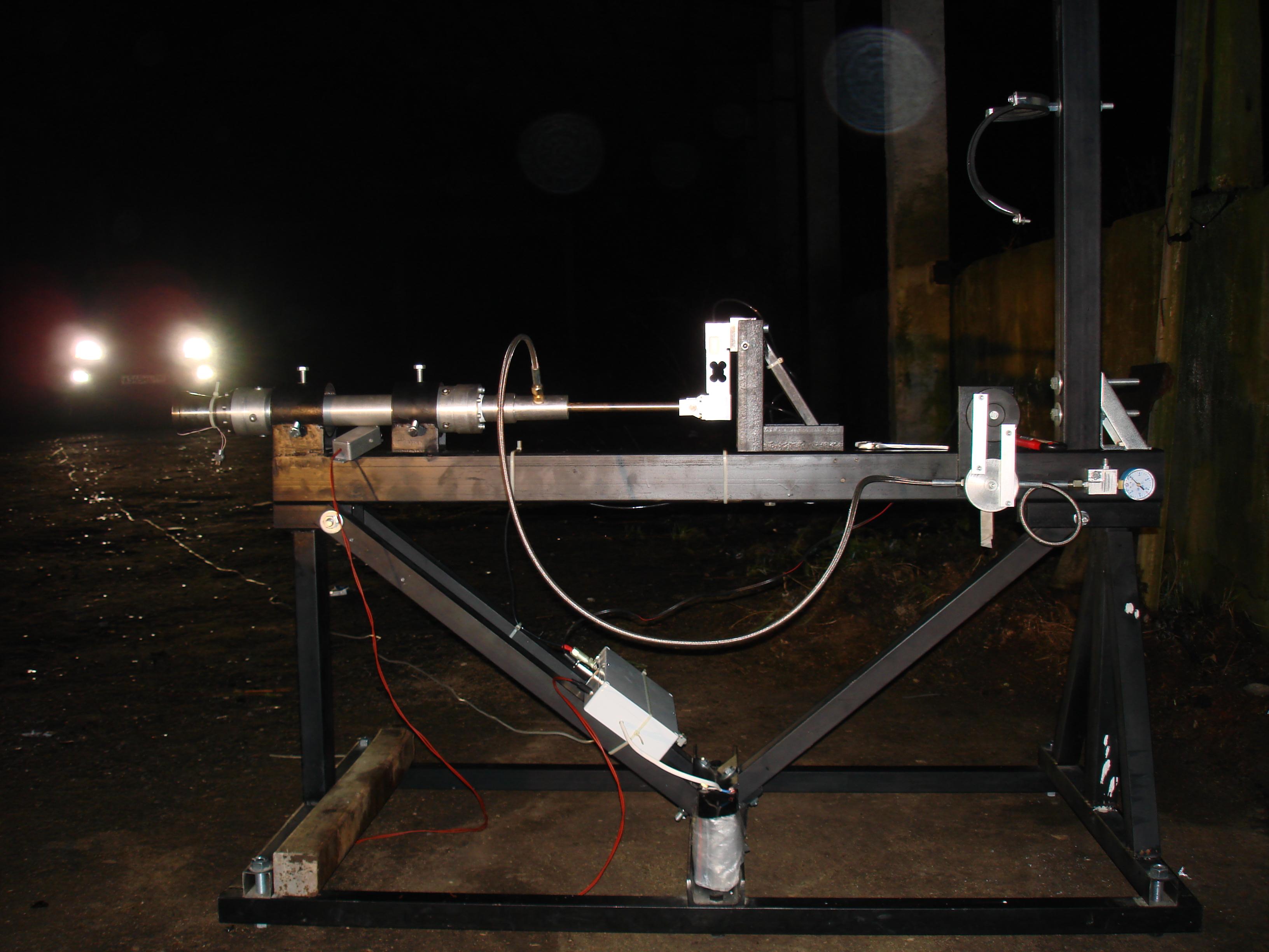
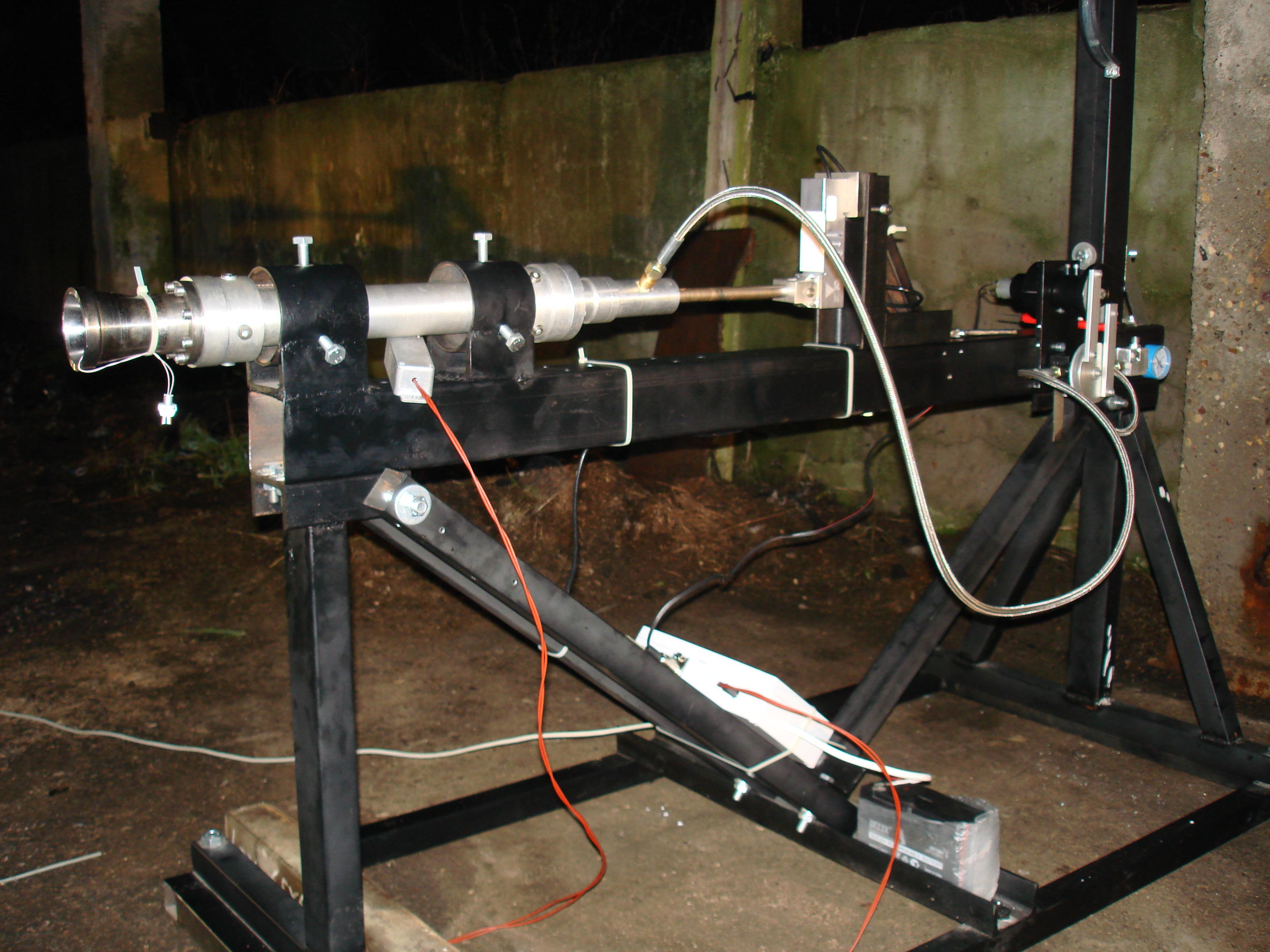
Anton <hybridrocket@yandex.ru>
That's my the first test stand for hybrid Nox/paraffin motor 330 poundsof thrust. The nearest purpose of our business - to make remotely operated pilotless vehicle (small airplane of rocket). It's the first and the only one of its kind project in Russia.
It has one electronic sensor for measuring of tractive force, connected to laptop;(20 meters long) remote control of electric valve and ignition, heating of the Nox tank.
In the near future we are going to modify stand with 1) second sensor for on-line datalogging of the Nox tank weight; 2) another manner of fastening of the motor; 3) another oxigener Lox tank (2,560psi).
We had only 5 fire tests with not good results (bad for motor only, not stand), but in one week we are will have good fire :)
Youtube movies of tests :http://www.youtube.com/user/HybridRocketRussia
click images to enlarge
Jeff Jakob
horizontal test standhttp://www.rockethigh.com/images/album/150test.jpg

50,000 N.S. Hybrid Test stand (click to enlarge)

3000 NS test (click to enlarge)
Paul Kelly
Here are some. There is another configuration we use it in. Wooden
blocks
allow it to just sit on the ground in nozzle up mode.


John Lyngdal
http://www.ieas.org/projects/John-Lyngdal-Otest.htmlThis was an earlier test of John Lyngdal's 4 x 136 mm motor.
The motor tested was a 136 mm O motor consisting of 4 BATES grains
each 8"
long, 4.8 in diameter, with a 1.62" port diameter. The propellant was
a 84% solids, non vacuum processed, AP/Al/SN/HTPB formulation.

click to enlarge
Loki Research
http://www.lokiresearch.com/pics/motor_testing.mpg
 |
 |
 |
 |
 |
This test stand was built by Alan Whitmore and Larry Mayberry (pictured).
It fires vertically, nozzle up, and measures both chamber pressure to 2500 psi and thrust to 500 lbs. Larry wrote the data reduction software in LabView. We've used it for testing over 100 different propellant formulations. Click any image to enlarge |
MARS UK
http://www.mars.org.uk/static.html
The main static test stand is designed to accommodate either a single
large rocket motor, or multiple smaller rocket motors such as the MARS
B4 Hybrid rocket motor. A load cell is fitted between the combustion chamber
and the static test stand to measure the motor thrust, and several sensors
are fitted to measure tank pressure, chamber pressure, as well as various
temperature sensors, and a spectrometer for exhaust plume analysis.
Sean McAndrew
Solid
http://mywebpages.comcast.net/seanmca79/teststand.htm

Above are some pics taken of our newly completed test stand. Of course we had to test it out with some cool motors. Click on the pictures for a larger version.
It is constructed of a 1/2" plywood base and three laminated 2 x 4's with a 3/4" ply face plate attached to them. Three 1/2" eyebolts hold a short section of 29 mm PML motor mount tubing into which the test motor goes. Four 1/2" landscaping spikes hold the stand firmly in place during tests.
The load cell is a TBS-40 from Transducer Techniques. It connects to
an INA125 amplifier chip that sends the amplified signal through 100' of
wire to a Dataq DI-151RS unit. This hooks up to my laptop that records
the data.

Pictures of my 54 mm test stand. It has a button load cell rated at 500 lbs. The tube slides on a nice roller bearing set up. I just need to get an amp set up for it and I'm good to go.
Microhybrid
http://mywebpages.comcast.net/seanmca79/hybrid/This was a group project for our Science Discovery and the Universe colloquium class of the College Park Scholars program at the University of Maryland. Group members included Dave Gerstein, Sean McAndrew, Sean Roark, and Eric Rodriguez. We were all second year students enrolled in the College Park Scholars SDU program. We are no longer part of the Scholars program, but will continue to work on the motor as time allows.

NASA Ames - Stanford
GOX/Wax 4000 LBF Motor - October 23, 2002See additional information here:
http://amesnews.arc.nasa.gov/releases/2003/03images/paraffin/paraffin.html
 |
 |
 |
 |
 |
Details of this motor have not been released yet but the 7.5" x 36"
motor has been successfully fired 40 times at NASA Ames.
4,000 LBF at 8 seconds, runs from 2 to 8 kG/sec mass flow depending on the test. Click any picture to enlarge. |

test fire 1 |

test fire 2 |
Richard Nakka
http://members.aol.com/ricnakk/static.html

The rocket motor was mounted vertically, with the nozzle facing upward, in a tubular holder. The bottom of the holder sat on a deflection bar which acted as a beam supported at both ends, with the load (motor thrust) acting downward at the middle of the beam (detail). The force transducer was mounted such that it's end was in contact with the deflection bar near the middle. As the motor would fire, the thrust would force the deflection bar to deflect downward, and in doing so, also deflect the beam of the force transducer.
http://www.geocities.com/exodus_trinity/sts5000f.html

click to enlarge |

click to enlarge |
See also Sugar Shot picture and link below
NASDA
National Space Development Agency of Japanhttp://www.nasda.go.jp/lib/nasda-news/1998/09/head1_e.html

H-IIA Solid Rocket Booster (SRB-A) at the Tanegashima Space Center
The chief objective of this test was to confirm the compatibility of the propulsion system design of SRB-A, the development of which has been steadily progressing. It was the first static test of the actual size motor. Figure 1 shows the overview of the tested SRB-A model.
* Maximum Thrust Force : 234 (217) tonf
* Maximum Pressure : 115 (108) kgf/cm2A
* Firing Time : 96.5 (94) seconds
courtesy of NASSA
http://www.rimworld.com/nassa/p5000.html

We built a simple stand out of wood, using a small "baby" scale to register
thrust. With the help of a video camera we where able to test fire the
sample motors and record the readings of the scale. Back in the shop we
viewed the videos and with stop motion, we timed the thrust registered
on the baby scale with the time on the video. The test stand was quite
easy to construct as can be seen in the photo. When the motor fired the
upward thrust forced the opposite end down onto the scale and we got our
readings. The stand is designed to reconfigure. Using a 25 lb. scale, we
are able to double the reading by shifting the center post to give us a
2:1 reading. We have since gone to a 50 lb. scale and can now read 100
lbs. of thrust. 100 lbs. of thrust is NOT necessary for "test" motors!!
Naval Air Warfare Center Weapons Division
http://www.nawcwpns.navy.mil/r2/fs/SkyProp.htm

Propulsion testing - vertical thrust |

Propulsion testing - horizontal thrust |

Propulsion testing - small engine test |
Static testing. Used for static testing of solid fuel rocket motors, from small motors and gas generators to rocket motors with 680 metric tons (1.5 million pounds) of thrust. |
Courtesy of NERO
Jeroen Louwers installing the static test stand for the hybrid rocket
motor system. Liquid oxidizer N2O, solid fuel a Polyurethane. The black
high pressure container, stores the laughing gas.

Orion Propulsion
http://www.orionpropulsion.com/email: support@orionpropulsion.com - Tim Pickens
Orion is situated on 120 acres on the outskirts of Huntsville, Alabama.
Our current test capabilities include multiple test cells capable of firing
bi-propellant liquid rocket engines with thrusts up to 50,000 pounds. In
addition, we offer a test cell capable of operating hybrid propulsion systems
with thrust levels up to 5,000 pounds. Orion is able to offer test services
at a very affordable rate because these capabilities are in-house, and
are typically easily configurable to each of your test requirements. Our
current test capabilities include a totally portable 28 channel high-speed
data acquisition and control system.
 |
Juan Parczewski
par2"at"sinectis"dot"com.arI'm Juan Parczewski from Argentina, and I'm attaching photos of my test stand.

My test stand is a vertical motor mounting, with two pressure gauge, one for chamber pressure and another for thrust. It fires vertically,nozzle up, and measures chamber pressure up to 2200 psi (15 megapascal) and thrust up to M class motors.

The motor move free in the vertical stand with adjustable screws to adapt different motor diameters up to 50mm. For motor with diameters up to 85 mm is necessary to change the vertical part of stand which is screwed to the horizontal part ofÝstand.
For more precision it is possible change the piston & cylinder to match the pressure gauge range to maximum motor peak thrust possible. The chamber pressure gauge was attached to the motor rear bulkhead. Both pressure gauges and pressure lines are filled with hydraulic oil. For exact thrust profile and pressure profile during the burn the record is done using one videotape for the two pressure gauges. Another videotape is used for recording the motor plume plus all test stand. The data collected from a videotape is put in a Excel spreadsheet, and for a given piston diameter it is possible to obtain thrust directly.
In the test above the propellant was a mix of potassium nitrate and
dextrose anhydride (KN 65%/DX35%). The low pressure in motor left at the
end of combustion the yellow in the nozzle that looks like a zinc sulfur
propellant. I attach portion of the spreadsheet of the obtained data,
it is Parczewski_burn_1.xls. That spreadsheet
show low Cf . I was consult to R. Nakka's ("master" in candy
type propellants) who recommend several tips to correct it . Finally the
solution was obtained via increasing the combustion pressure and reducing
the angle of exit of the nozzle.
Really I must to admit that is a very good example of application
of this tool (the test stand) to find and fix problems like this.
Tip toes: since they are screwed so they are flexible, spikes for soft land, studs for attaching to other structures or plastic head for hard land like concrete.
Recently I incorporated a handle to make easy the transport.
Cheers
Propulsion Polymers
http://www.propulsionpolymers.com/Marcus Leech
mleech "at" nortelnetworks.com

click to enlarge |
This shot was taking during the certification test sessions done at
CTI in June of 2002. That's an I-140 firing in the stand.
This one was built by Bill Wagstaff. We have various sized load cells from 250lbs up to 1500lbs. Data collection is via a DataQ 12-bit serial A/D module. We've also used a LabJack for data collection. The stand has been used to test fire motors from 22mm up to 63mm. We're going to upgrade it so that we can test-fire Glen Hilliers 6" liquid bipropellant sometime this spring. |
RATTworks
http://www.rattworks.night.net/InTheWorks/Bi-Prop/index.html

click to enlarge images
Static test of R.A.T.T. Works L1000 Nitrous Oxide and Liquid Alcohol
Bi-Propellant

Redstone
http://www.redstone.army.mil/history/teststand/welcome.html

When fabrication of the first REDSTONE began in 1952, the Army was faced
with a dilemma: refining a missile depended on a propulsion test stand.
But an inflexible law stated that no funds for research and development
could be spent constructing facilities. Rather than wait for funding, REDSTONE
engineers designed an interim test stand for $25,000, the maximum amount
allowed for constructing facilities without congressional approval.
Rocket Hunter
http://www.rockethunter.com/Joe Mullin

Stand mounted in receiver |
close up of 500 lbf load cell mount |

Ready to fire |
Motor burning |
Click to enlarge images
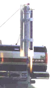
Here you see a RATT K240 hybrid
in a truck mounted test stand using standard trailer hitch components.
The load cell is an Aerocon
500 pound cell using an eyebolt as a support, hanger, and thrust plate.
Another bumper mounted thrust stand
Rowan University
College of Engineering, Hybrid Rocket Motors
http://users.rowan.edu/~marchese/rockets05/design-project.html
 click to enlarge
Courtesy of RRS.org
http://www.rrs.org/Projects/Static_Tests/static_tests.htmlJim McKinnon's 1000 lbf thrust LOX / Jet A Static Test. Jim's injector
is using 28 O-F-O Triplets with a O-O-F-O-O Pentad element in the center.
The combustion chamber was a surplus Atlas vernier. The large gauge is
measuring chamber pressure.

Korey Kline's Nitrous oxide / HTPB engine is test fired at the MTA.

From Korey about this stand:
I wanted a thrust stand that would give me peak thrust and peak
chamber
pressure without a bunch of electrical instrumentation and associated
AC
power requirements. The basic Idea is to convert pounds thrust into
pressure
(PSI) that you can now read with a pressures gauge. I used a 1.125
inch dia.
cylinder filled with oil with a pressure gauge attached to the bottom
of the
cylinder. As the motor is fired it puts a load/force directly on the
1.125"
cylinder. The area of a 1.125 " dia cylinder is almost exactly one
square
inch, so any measurement I get from the pressure gauge is a direct
readout
of thrust in pounds. You can use other sized cylinder but you then
have to
go through a conversion factor based on cylinder size. I purchased
two liquid
filled gauges with a "Peak" pressure needle from McMaster-Carr. This
gauge
can now be videotaped for exact thrust profile during the burn and
the peak
pressure needle records the peak thrust. The chamber pressure
gauge was
designed much the same, with the obvious exception that it was attached
to
the motor rear bulkhead.
I was using this for very early hybrid testing at less than 500 lbs
thrust.
If you use an "off the shelf" cylinder you need to make sure it can
take the
peak thrust (PSI) or design your own with thick walls. Hybrids tend
to be
constant(ish) thrust so the peak pressure data was adequate for first
pass
(in the field) thrust information. If you were to use it to test a
progressive or regressive thrust solid, then the video would be more
useful.
Something also to think of is if you have "Combustion Instability"
or
Chuffing", the peak pressure gauge will only record the highest "Pulse"
and
throw off your thrust data.
Bill Spadafora
billspad "at" comcast.net
The stand was something I built for a science fair project some time
around 1967. It's just a spinning drum with pressure sensitive paper and
a scribe. I remember having a hard time finding the right spring. The one
I ended up using was part of one of my mother's hair rollers! The white
tank is a vacuum tank. As part of the project I fired the engines in a
vacuum. There's also footage of it being fired with the nozzle of the motor
under water. The last part shows it being fired indoors in an oven. I can't
believe that it didn't occur to me to tie it
down. I can't recall how I got away with firing it indoors. I'm fairly
certain no one else was home at the time.
download a movie of Bill's test stand
http://home.comcast.net/~billspad/stand.mpghttp://home.comcast.net/~billspad/stand.mpg
Sugar Shot

Swiss Propulsion Laboratory
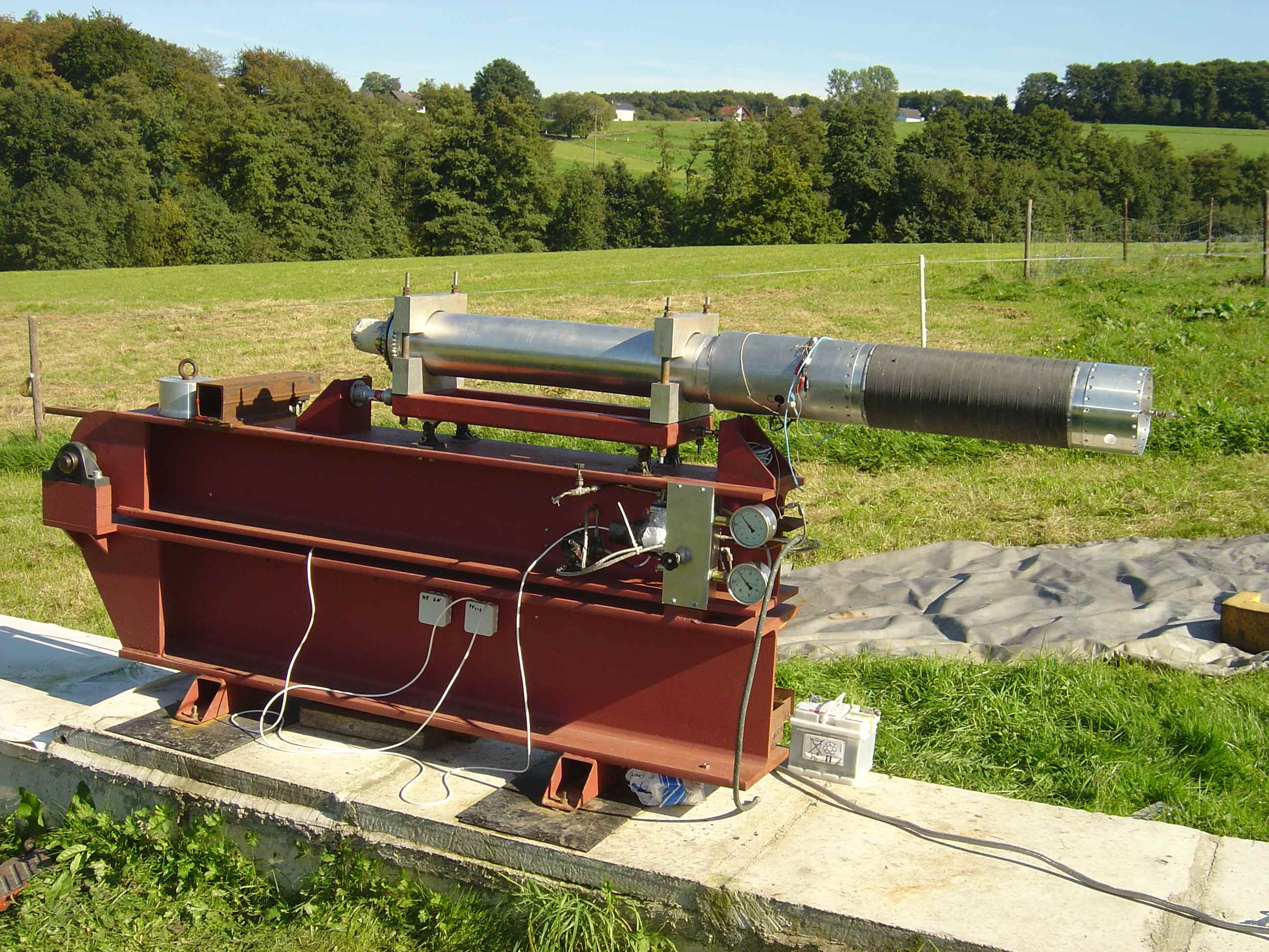
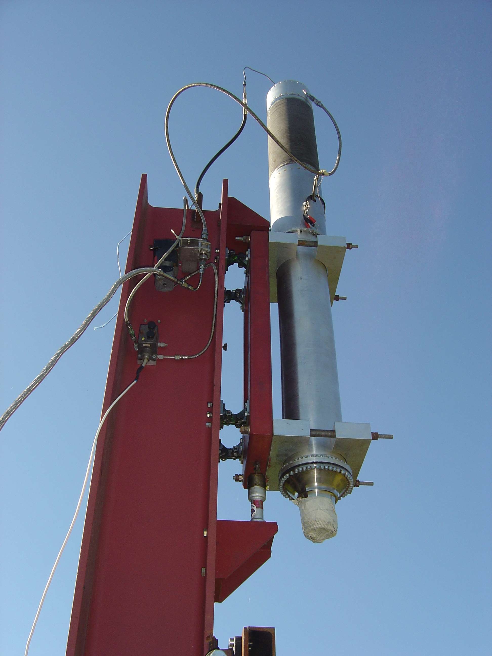
http://www.spl.ch/temp/Test-stand/Bruno Berger

To test and characterize engines, fuels etc. a thrust test stand is
essential. In the frame of an exhibition of the Space forum 2001 (27. January)
held by the Swiss Astronautics Association, we presented our new test stand.?
With this test stand both liquid engines as well as solid propellant
motors with thrust up to 100 kN (10 metric tons) can be testedÝ The measuring
table is mounted on 8 hysteresis free "Flex"-joints (with integrated safety
stop extensions). The table is made of aluminum and has many integrated
"T" grooves for easy mounting of different kind of engines, valves and
other equipment. The load cells can be exchanged to the respective measuring
range.Ý At the moment, a load cell for max. 25 kN is installed.Ý The heavy
steel frame is additionally filled with concrete to suppress possible oscillations.
For transportation the Test Stand fits on a standardized "Europalett".
The photo shows the test stand with the "TETHIS-I" 8 kN solid booster.
Unity
Unity IV hybrid rocket project providing students from Brigham Young University, Utah State University, the University of Utah, and Weber State University the opportunity to design, test, build, and launch a sounding rocket capable of carrying a small scientific payload to 130,000 feet using hybrid propulsion.

University of Colorado at Boulder
http://www.mach-sr1.org/The MaCH-SR1 hybrid rocket launch vehicle is a student-driven project that is currently under development at the University of Colorado in Boulder. The core team consists of nine students, but there are also advisors and many other interested people contributing in one way or another.
The specific long-term technical goal of this project is to build a sub-orbital rocket that is capable of:
* Altitude goal of 78 miles (125 km) sub-orbital space flight
* Payload weight goal of 10 lbs (4.5 kg)
* Reliable 13,000 lbf (58 kN) throttled LOX/HTPB hybrid engine
* Recoverable/Reusable airframe
The current team is focused on meeting the following objectives:
* Design and build
a 5000 lbf (22 kN) engine
* Static Test
the engine
* Prepare the engine for integration into a flight vehicle.


Click to enlarge images
US Rockets

click to enlarge - 18mm-75mm Horizontal/Vertical stand
9 inch solid test stand
http://v-serv.com/-upload/9test4.jpg
4 inch solid in 9 inch stand
http://v-serv.com/theproject/images/4Cstatic.jpg
http://v-serv.com/theproject/images/4static2.jpg
6x96" motor in 9 inch stand
http://v-serv.com/theproject/images/6Sstatic.jpg
Top view
http://v-serv.com/theproject/images/6post.jpg
Side view
http://v-serv.com/theproject/images/PRSgroup.600.jpg
38mm uninstrumented fixture (tube topper)
http://v-serv.com/theproject/images/qual.jpg
Robert Watzlavick
http://www.watzlavick.com/robert/rocket/testStand/index.html


The test stand has taken way more time to put together than I imagined.
In fact, it's taken about 5X more time than the design and fabrication
of the uncooled engine.
I finally finished the failsafe control unit. It's purpose is to control
the various remote devices (relays, solenoids, ignitor, etc.) during the
test. It also provides for a remote control box that includes a dump switch
and some status indicators. The card interfaces to a National Instruments
PXI-6527 isolated DIO board and will be controlled by the test program
in LabVIEW.
I used Eagle Schematic for the drawings. It runs in Linux and Windows
and they also have a free version (which I'm using). I have hand sketches
of the overall instrumentation setup which I'll convert over to Eagle
when I get some more time.
I added a separate fill port to the LOX tank to make it easier to get
it closed back up after filling based on my tests with LN2. The internal
threads on the tank got iced up real bad and I couldn't thread the burst
disk fitting back all the way in. The new tube connector has external
threads on the top so it is much easier to cap it off after I'm done filling
it.
This test stand is designed for engines in the 100-500 lbf thrust range.
I plan to test several engines before I decide on a flight-worthy version
so I wanted it to be as reusable as possible.
There are standard pressure transducers for the propellant tanks along
with the compressed air supply and a dynamic Endevco pressure transducer
for the chamber pressure. A 500 lbf load cell measures thrust and there
are up to 8 thermocouples that can be placed on the engine and around
the test frame as needed. All the actuators and sensors are controlled
by a mix of National Instruments and custom hardware. The data acquisition
and control software is written in LabVIEW.
I made several adjustments to the test setup after cold LN2 testing before
the hot fire, including a separate fill port for the LOX tank to make
it easier to get it closed back up after filling. I also switched to a
larger air actuator on the ball valve since it was pretty hard to turn
at low temperatures.
More details on the test stand:
http://watzlavick.com/robert/rocket/testStand/index.html
More details on the uncooled chamber test:
http://watzlavick.com/robert/rocket/uncooledChamber/tests/index.html
Jimmy Yawn
Analog Test Stand Made From Trash
http://www.jamesyawn.com/teststand/index.html

I don't know if you are interested in the very low-end of the test
stand spectrum, but if you are, I have a competitor. It is perhaps
one
notch above the post-hole digger. It looks like a science-fair
"honorable mention," but I have managed to
get some useful data from it. I may try to improve it one more
time
before moving on to a digital model.
![]()
Warning: All liability waived! Rocketry is an inherently dangerous undertaking.
Make your choices and take personal responsibility for the outcome of your experiment!
Protect your privilege to fly rockets by not making the headlines or becoming a statistic.